Summary
This guide describes the process of adapting a standard Motorola PMN4107B PTT (speaker-microphone) for use with the MIC-CONNECTOR (M002) interface. It covers cable preparation, RJ45 pinout, and proper crimping procedure.
To complete this modification, you will need the following tools:
• RJ45 crimping tool
• Wire cutters
• Wire stripper
• New RJ45 connector
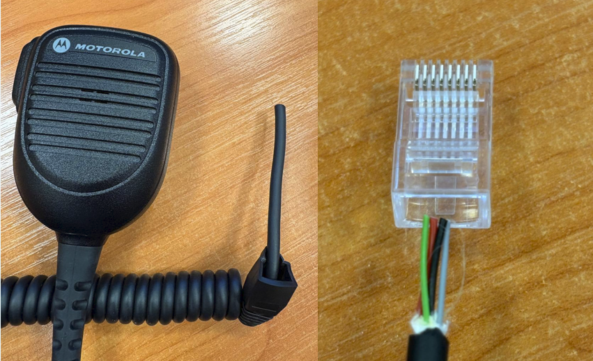
Before you begin make sure to slide the protective rubber boot onto the PTT cable before cutting wires and crimping the connector. Once the connector is crimped, it will be impossible to fit the boot onto the cable.
Step 1: Cable Preparation and Stripping
1. Cut off the original Motorola connector from the PTT cable using wire cutters.
2. Slide the protective rubber boot onto the cable and push it further down the wire so it stays out of the way during work.
3. Carefully strip 20 - 25 mm of the outer cable jacket, taking care not to damage the inner conductors.
4. Locate the inner strength strand (nylon cord) together with the brown wire and cut both off flush at the edge of the outer jacket. The brown wire is not used in the M002 mic adapter wiring scheme.
5. Straighten the remaining 4 wires (green, red, black, grey) and arrange them strictly in order, parallel to one another.
Step 2: Trimming to RJ45 Size
1. Firmly pinch the 4 conductors with your fingers and trim the excess so that the length of exposed wires is exactly 12 - 13 mm from the edge of the outer jacket.
You do not need to strip the individual insulation from the color-coded wires. The RJ45 connector blades will pierce through the insulation on their own.
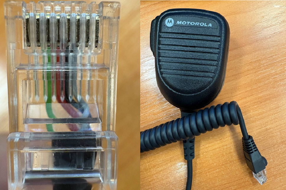
2. Insert the wires into the RJ45 connector (latch facing down) according to the following pinout table:
|
RJ45 Pin Number
|
Wire Color
|
Signal
|
|
1
|
(empty)
|
-
|
|
2
|
(empty)
|
-
|
|
3
|
Green
|
PTT (Push-to-Talk)
|
|
4
|
Red
|
MIC (Microphone)
|
|
5
|
Black
|
GND (Ground / Common)
|
|
6
|
Grey
|
HOOK (Hang-up sensor)
|
|
7
|
(empty)
|
-
|
|
8
|
(empty)
|
-
|
If the wire colors differ.
The manufacturer may change the internal color coding of conductors across different production batches of Motorola PMN4107B PTT.
If, after removing the outer jacket, you discover wire colors that do not match the table above, do not proceed with crimping blindly. In this case, you must first identify the correct contacts using a multimeter, or contact TRBOnet support team (support@trbonet.com) to obtain an up-to-date color mapping reference.
Step 3: Inspection and Crimping
1. Push the wires all the way into the connector until they stop. Look through the transparent end of the connector to verify that all 4 conductors have reached the front wall and that the thick outer cable jacket has entered the RJ45 housing by 5 - 6 mm for secure strain relief.
2. Insert the connector into the crimping tool socket and squeeze the handles firmly until they stop.
3. Slide the protective rubber boot over the installed RJ45 connector. The modification is now complete.