Do not rely on this document for warranty decisions. Warranty replacement is determined by Sales and Swift Development teams.
Diagnostic procedure for Swift Agent A200m and A200 units experiencing constant reboot cycles. Covers model identification, firmware testing, and multimeter diagnostics.
Identifying the Model of Swift Agent Device and Mode of Operation
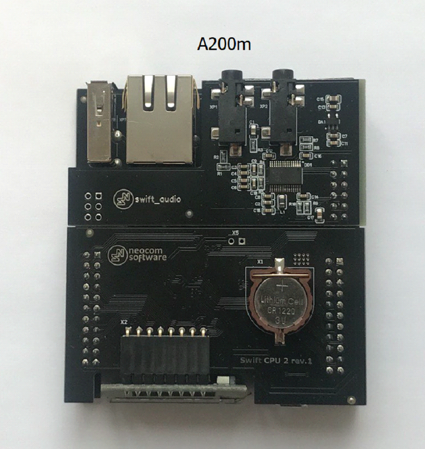
Swift Agent A200m:
- Has no SD card slot
- The serial number of A200m has a mixed alphanumeric format XXXXXXXXXXXX (12+ characters)
- Sticker with serial number is white
- Saved Swift CPS configuration has model name A200m in Device information tab
- CPU and GATE PCB color and looks:
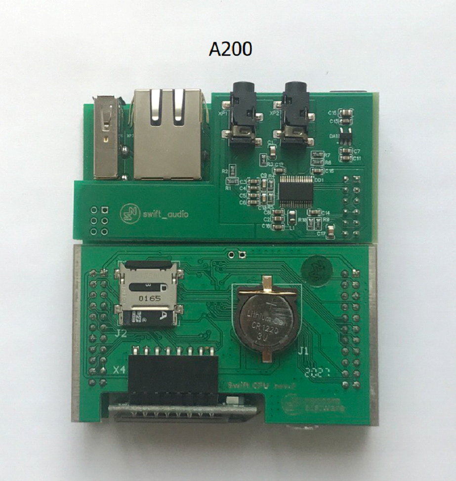
Swift Agent A200
- Has an SD card slot
- The serial number of A200 device has the following format: XXAXXX (6 characters), where X are digits
- Sticker with serial number is black with white characters
- Saved Swift CPS configuration has model name A200 in Device information tab
- CPU and GATE PCB color and looks:
1. Confirm previous mode:( or )
2. Confirm any recent changes: PSU replacement, firmware change, mode change, equipment swap
Firmware Change and Control Radio Detach Test
1. Detach Swift Agent from Control Radio
2. Change mode of operation to
3. Verify whether this rectifies the issue
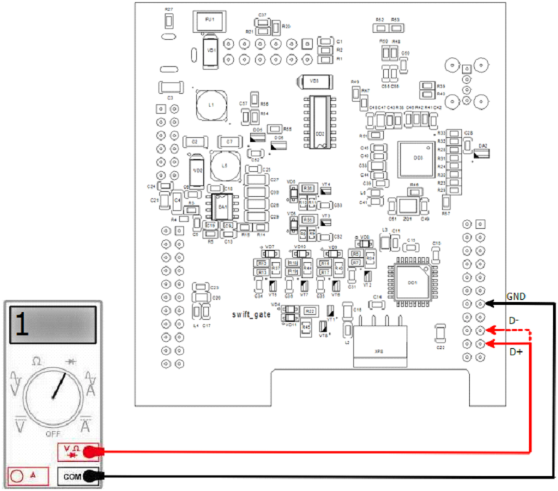
Diagnostics of CPU PCB Using Multimeter
1. Remove the cover on the back of the case, pull out the set of PCBs
2. Using a multimeter Diode Mode, check the USB connection lines to the Control Radio - Black probe on GND, Red probe on lines D+ D-. Infinite voltage should be shown
3. Using a multimeter Diode Mode, check the USB connection lines to the Control Radio - Red probe is on GND, Black on lines D+, D-. The multimeter should show the same (on D+ and D-) voltage decrease value, around 0.5-0.7V
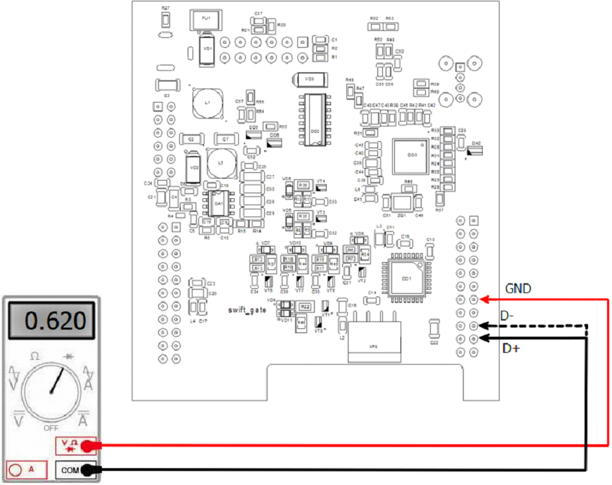
4. If multimeter does not show reference values - CPU PCB is malfunction