Troubleshooting Swift Agent Power-On Issues
The article was successfully sent to the email
Do not rely on this document for warranty decisions. Warranty replacement is determined by Sales and Swift Development teams.
Diagnostic procedure for Swift Agent A200m and A200 units that do not switch on. Covers model identification, visual inspection, PCB isolation, USB enumeration checks, and multimeter measurements.
Identifying the Model of Swift Agent Device and Mode of Operation
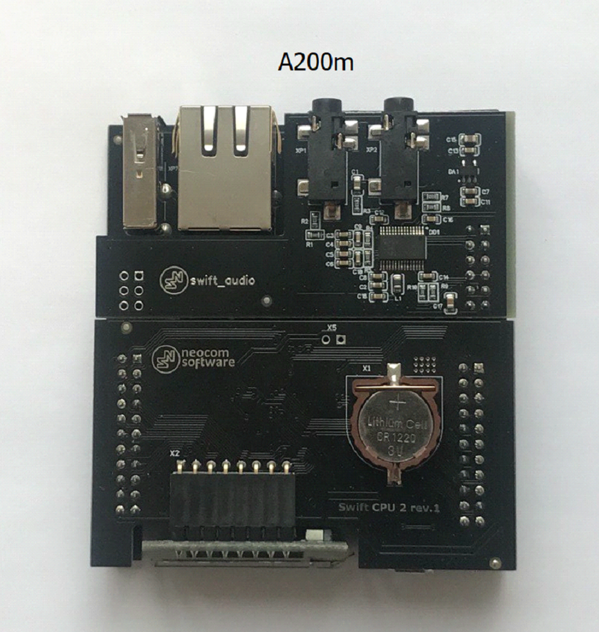
Swift Agent A200m:
- Has no SD card slot
- The serial number of A200m has a mixed alphanumeric format XXXXXXXXXXXX (12+ characters)
- Sticker with serial number is white
- Saved Swift CPS configuration has model name A200m in Device information tab
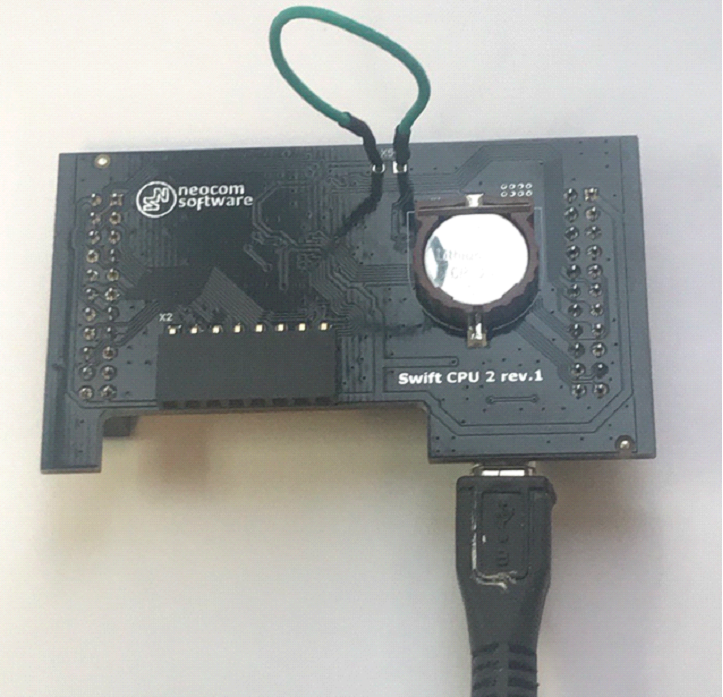
- CPU and GATE PCB color and looks:
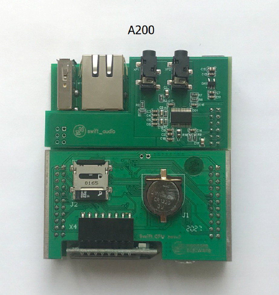
Swift Agent A200
- Has an SD card slot
- The serial number of A200 device has the following format: XXAXXX (6 characters), where X are digits
- Sticker with serial number is black with white characters
- Saved Swift CPS configuration has model name A200 in Device information tab
- CPU and GATE PCB color and looks:
1. Confirm previous mode: ( or )
2. Confirm any recent changes: PSU replacement, firmware change, mode change, equipment swap
Quick Visual and Smell Inspection
• Check the CPU board, its elements, and battery for damage caused by voltage surges or incorrect connection/disconnection of the control station
• Pay attention to the burnt PCB smell - if any element is burned, there may be a burning smell
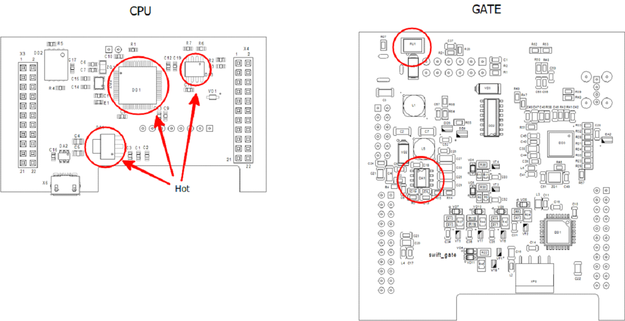
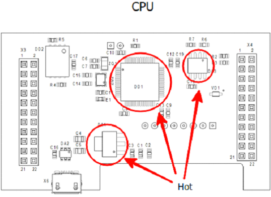
• Some elements on the board may become hot (above 40 degrees Celsius). Try to touch the CPU board carefully to detect the place of strong heating
• Possible places of heating and/or burnt PCB smell are marked in red circles:
Quick Swap Test
• If you have a donor device of same model, try to switch components between them for fast identification of the malfunction part
Diagnostics of CPU PCB on Disassembled Device
Assembly after diagnosis is performed in the reverse order
1. Remove the cover on the back of the case, pull out the set of PCBs
2. If there is an SD card installed on the CPU board (A200), remove it
If the Swift Agent starts working after removing the SD card, try to format or replace the SD card. The agent can work fully without an SD card, only logs are stored on the SD card, SD card icon will blink on the display, but the operation is not affected
3. Disconnect the OLED (display)
4. Disconnect the AUDIO PCB
5. Disconnect the CPU (upper) PCB from the GATE (lower) PCB
Carefully inspect all Swift Agent PCBs for damaged elements and printed circuits. If you detect damaged elements, take a clear photo of the damaged areas
6. Connect the OLED (display) to the CPU PCB only
7. Connect the CPU PCB with attached OLED via the Micro-USB connector on the CPU board to the Computer USB port
8. Try to detect possible heating of the marked elements during 2-3 minutes of connection
9. If the display lights up after connection and the Swift CPS configuration can be read/written using Swift CPS - the CPU PCB board is functioning
10. If the display does not light up:
- Disconnect the OLED board from the CPU PCB and connect only the CPU PCB to the computer
- If the Swift CPS configuration can be read/written using Swift CPS - the CPU board is functioning, most likely the OLED is faulty. Try to replace the display with a working donor copy (the displays are compatible between M models and the previous version)
Without the OLED board, the Agent retains functionality, it just does not display information
11. When connecting the CPU PCB to Computer, note which device is shown:
- indicates normal mode
- indicates firmware recovery required
12. If the display does not light up, there is no device in Windows device manager, and there are no signs of heating of the elements, try to close the jumper on the CPU PCB:
• This should activate the bootloader startup process and the device should be detected as . If this does not happen, the CPU PCB is faulty
Diagnostics of CPU PCB Using Multimeter
1. Remove the cover on the back of the case, pull out the set of PCBs
2. Connect the device to external power supply via a standard 12V power connector
3. Measure the voltage on the CPU PCB:
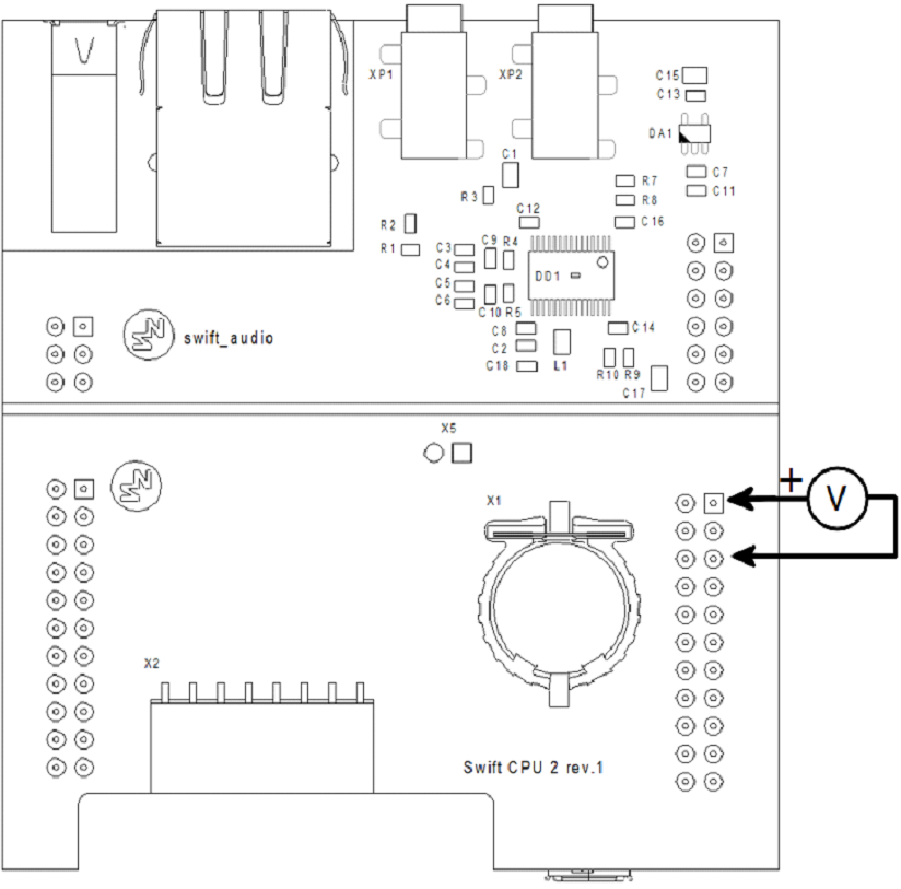
• The voltage should be 3.3V. If the voltage does not match - one of the PCBs (CPU or GATE) is malfunctioning
4. To determine which of the PCBs is malfunction, separate the boards and measure the voltage on the GATE PCB (lower board):
• If there is 5V on the GATE PCB (bottom board) but no 3.3V on the CPU PCB (top board) - CPU PCB is malfunction
5. Using a multimeter Diode Mode, check the USB connection lines to the Control Radio - Black probe on GND, Red probe on lines D+ D-. Infinite voltage should be shown
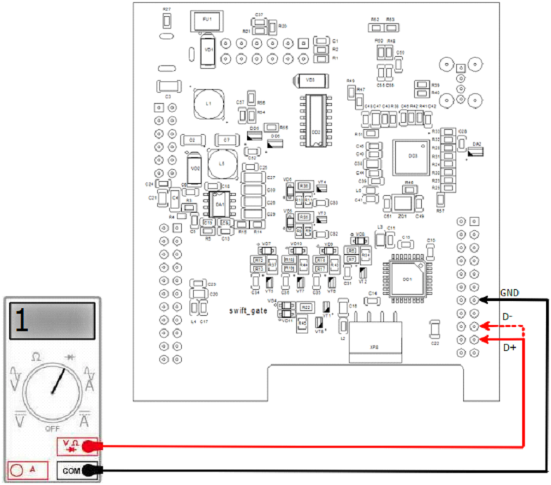
6. Using a multimeter Diode Mode, check the USB connection lines to the Control Radio - Red probe is on GND, Black on lines D+, D-. The multimeter should show the same (on D+ and D-) voltage decrease value, around 0.5-0.7V
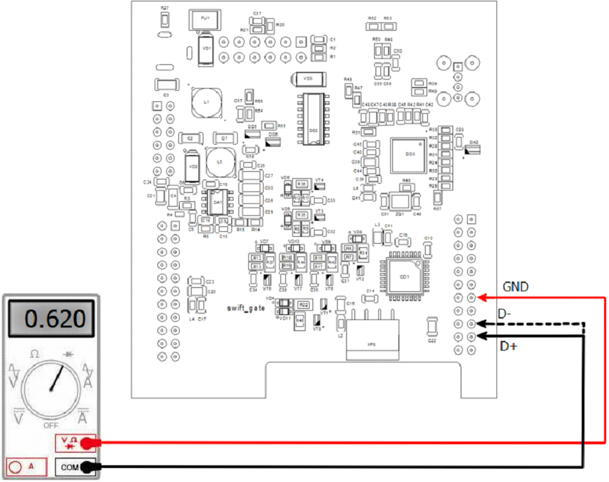
7. If multimeter does not show reference values - CPU PCB is malfunction
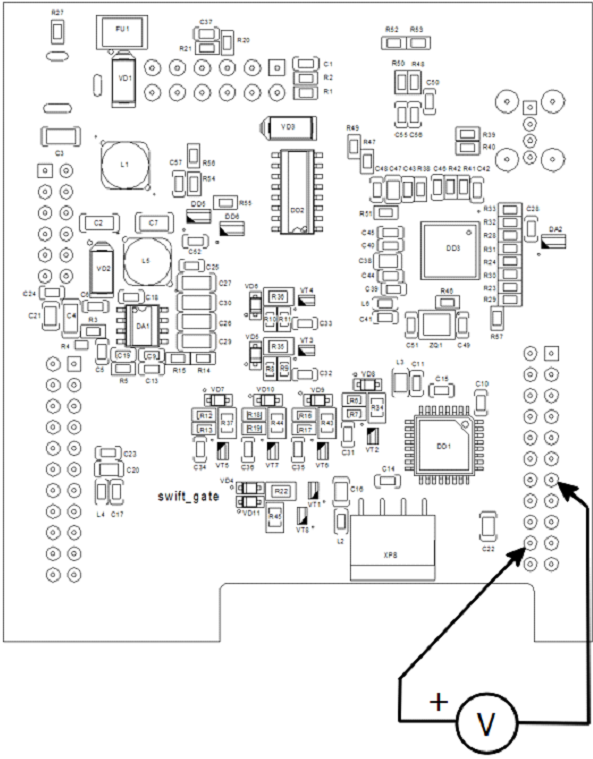
Diagnostics of GATE PCB Using Multimeter
1. Disassemble the Swift Agent and separate the top (CPU PCB) and bottom (GATE PCB) PCBs
2. Connect only the GATE board to external power supply via a standard 12V power connector
3. Measure the 5 Volt voltage at the converter:

4. If there is no voltage, the converter on the PCB is malfunctioning